Monthly Archives: February 2023

Special Blog Post for 20230131 – Accessory Building Project Update

There are no photos for this post. ]

TUESDAY 31 January

Looking back on the last two (2) weeks, it had been an amusing, confusing, slightly sad, but exciting and gratifying time.  The electrical service work for the barn (with upgraded power for the house) was done.  The crews had all been very professional and had done the work well.  But they were also friendly and helpful, as they put up with my presence, questions, and photography with good humor.

The only question that remained, power wise, was when a crew would show up to change out the pole in the SE corner of our yard.  This pole does not have a transformer on it, but it does have the tap for our Comcast/Xfinity broadband cable to the house.  It supports the electric distribution wires that run E-W down our side of the street, along with the AT&T and Comcast cables.  These lines also T-off and go across the street to a pole in our neighbor’s yard to supply services to their house.  It does not have a transformer on it, but it looked to me like the T would make installing a new pole tricky.  I guess I will find out just how it’s done when someone shows up and does it, assuming I am at home when the work happens.  Never once have we been contacted in advance to let us know that a crew was scheduled to be onsite.

…..

Special Blog Post for 20230130 – Accessory Building Project Update

This post has 9 photos. ]

MONDAY 30 January

Expect the unexpected, right?  For me, that’s inline with the idea that “things happen beyond our control, but how we deal with them is up to us.”  After a week of somewhat strange communications, but no additional work, a crew from Rauhorn showed up today.  Rauhorn is another DTE contractor.  I think they do both overhead and underground work, and were prepared for both, but the remaining work was mostly underground.

The small excavator was used to “hang” the large spool of 3-conductor, 3/0 AWG service conductor cable so it could unwind easily as it was fed into the 2” Schedule 40 PVC electrical conduit through the bottom of the meter enclosure.  The conduit is visible coming out of the bottom of the meter enclosure and into the ground.


I was already familiar with Rauhorn as they did some of the work on the power upgrade for our neighbor’s house across the street back in mid-November.  When they were finished doing that work, I asked the crew chief if he had a few minutes to came over and look at what I was planning to do, conduit-wise.  He did, and gave me some very useful suggestions as to how to do it to make it easier on whatever underground crew eventually showed up to install the electrical cable to the barn.

The trench from the open end of the conduit towards the pedestal with the service conductors already pulled through.  The open end of the conduit is at least 24” below grade, but they did not trench that deep all the way to the base of the pedestal.  There is no conduit from this point to the pedestal, as the cables they installed are rated for direct burial.  That also means it does not matter if dirt or water gets into the conduit.  The conduit was optional, but it saved me the cost of having DTE (or a contractor) dig the whole trench, allowed me to route the cable away from some trees, and will provide external protect in the event that someone ever decides to dig in this area.


This crew was here “to complete the installation of power to the barn,” but were surprised to find that major pieces of the work they planned to do had already been completed, specifically the pedestal and the 350 kcmil service drop conductors.  (I was not surprised that they were surprised.)  But they were fine with the situation.


The trench for the barn service conductors to the base of the pedestal.  The top cover of the pedestal has been removed to allow access to the junction blocks.


I explained about the advice I got from one of their guys before trenching in the 2” Schedule 40 PVC electrical conduit, and pointed out the stake that marked the location of the free end near the new pole.  With the small excavator (12” bucket), they came prepared to dig a trench, but only had to use it to unearth that end of the conduit (and hang the large cable spool).  They dug up to the base of the pedestal by hand as there were live conductors buried there.


The 3-conductor, 3/0 AWG service conductor cable being fed into the 2” Schedule 40 PVC electrical conduit through the bottom of the meter enclosure.

They were glad to have the 7/16” rope already through the conduit and used it to pull the 3/0 AWG, 3-conductor underground service conductor (USG) cable from the meter enclosure up to the pedestal.  To does this, they suspended a large spool of the USC cable off of the excavator bucket so that it could unwind horizontally.  The free end of the cable was attached to the rope in the meter enclosure in such a way that it would not pull loose.  One guy helped guide/feed the cable into the conduit attached to the bottom of the meter can, while two guys pulled it through the conduit from the other end by hand with the rope.  They stopped with enough cable still at the meter enclosure to make the connections to the meter lugs.


The barn service conductors through the conduit and up through the pedestal.  They were then trimmed to the length needed to fit into the junction blocks.  At this point, the crew was dealing with live (energized) un-fused wires.  They knew what they were doing, and had the right personal protective equipment, but this was still not work for the faint of heart.

On the other end, they opened the top pedestal cover and routed the cable from the barn up through the bottom and out the top.  They cut each wire to length to fit into the large junction blocks that were already there.  As they were working, I noticed that one of the hot conductors that had been terminated by the previous crew had about an inch of exposed conductor below the insulated junction block.  That was a major oversight that could have led to a short or an energized pedestal cover (the covers are made of metal).  Rather than try to cut the live exposed metal strands shorter, one of the guys removed the conductor from the junction block, wrapped electrical tape around it up past where the wire insulation ended, reinserted it, and tightened it.  He was wearing proper personal protection equipment, (PPE), and clearly knew what he was doing, but all of this was on a live, unfused wire.


The barn service conductors enter the meter enclosure from the large conduit on the left and are attached to the meter socket lugs at the top.  (Meter enclosures/sockets have been built this way for a long time, going back to when almost all utility conductors ran overhead and entered the meter enclosure from the top.)  The black, red, and bare/aluminum conductors attached to the bottom meter lugs are the service entrance conductors.  They are enclosed in a sheath as they exit the meter enclosure at the lower right and go through a hole in the side of the barn, where they are then routed up into the bottom of the main load center and connected to the main breaker (first disconnecting means) at the top of the enclosure.  Because this is a sheathed cable assembly, it is not required to be in conduit.  Although I would have preferred that it was, this work was done by the electrician, under permit, and inspected/approved by the County.  As such, it was not appropriate for me to change it (and would have been a bit of work to do so).


ep was to install a meter, at which point we finally had power to the barn!  I closed the main circuit breaker (which serves as the main disconnect for the barn) and then closed the circuit breaker for the Siemens FirstSurge surge protection device.  Two green lights indicated that I had power to both buses of the panel.  (I later checked the GFCI receptacle the electrician had installed way back when, and confirmed that I had 120 VAC and the GFCI feature worked.)


The trench with the barn service conductors bending into the bottom of the pedestal. This photo shows that the wires, which are direct -burial, are not buried very deep at this point.


The final step was to put the upper cover back on the pedestal and secure it, and use the excavator to push dirt back into the trench and up to the base of the pedestal.  One of the crew members said they would transmit the meter number to DTE.


Almost done.  They meter was seated in the socket and, just like that, we had power to the barn!  It was obviously nice to finally have power to the barn, but the five (calendar) days it took to do this work were fascinating for me to watch and document.  I learned a lot from the various crews, who were all (mostly) good sports about me being around with a camera and asking lots of questions.

As the trench by the pedestal was being filled back in, I took this photo to show that the bottom cover of the pedestal does not extend very far below grade, and the wires going to barn bend almost immediately as they leave the pedestal towards the conduit.  The same is true for the service conductors going to the house.  Any digging within a 5’ radius of this pedestal would risk contact with these conductors.  They are all insulated, of course, but still …


I e-mailed the DTE case manger and the planning consultant (with a couple of photos) to let them know the work had been completed and I had power to the barn.  As far as I knew, I was now done dealing with DTE other than to get the account number for the new meter and pay the bill each month.


The meter enclosure cover installed and secured.

Although I was not going to pull an electrical permit until mid-March, and probably not start wiring the barn until early April, it was time to work on the electrical plan in earnest.  As soon as we returned from our travels I would need to be ready to start buying electrical materials and devices and staging them in the barn.  Of course, I needed the big roll-up doors in order to do that.

Special Blog Post for 202301(24-29) – Accessory Building Project Update

There are 3 photos in this post. ]

TUESDAY 24 January – SUNDAY 29 January

When the Motor City Electric Utilities crew finished their work on Monday the 23rd, the project was well on its way to completion, but not quite finished as we still did not have power to the barn.  During the week, I got an e-mail from our DTE planning consultant with contact information for the “case manager” who would schedule the work, and letting me know that I would now be dealing with her from now on.  I e-mailed her and introduced myself, and cc:d the planning consultant.  I included photos, and let them know the work was almost completed, and that all that remained to be down was to pull the underground service conductors from the barn meter enclosure to the pedestal, terminate them at both ends, and install the meter.  Once again, the reply that I received was basically “what?”

By this point, and after discussion with some friends, I had come to the conclusion that my customer satisfaction survey reply, and subsequent conversation with a customer service representative, appeared to have triggered a response from DTE.  While I was glad that the work was getting done, I was saddened that the people responsible for planning and scheduling the job, and with whom I had worked closely, appeared to be unaware that the work was taking place.  Indeed, the planning consultant indicated that he had only just released the work orders for scheduling.  And that was not right; it’s never right to bypass people.  Go through the reporting chain to the people responsible and make a higher priority of the work, sure, but do not go around them.

Sometime during this week, the builder also got word that the roll-up doors would not be available by the end of the month and he was trying to pin down a delivery date.  At this point, it almost didn’t matter.  We would be traveling from late February to early March, and I would not be starting the wiring until we got back.  In fact, I had to do some painting even before the electrical work, which I couldn’t do until the temperatures were warmer and would stay that way overnight.  Also, I had no interest in doing electrical work in the cold and neither did Marty, who offered to come down and help.

The main load center for the barn with the Siemens FirstSurge device mounted externally, lower right and connected to a 2-pole, 20 Amp circuit break, lower right in the enclosure.  This was the only wiring I intended to do on the barn before apply for an electrical permit in mid-June, but I wanted this device in place before the electrical service was energized.

I did, however, manage to accomplish two small things in the barn this week.  A while back I bought a Siemens FirstSurge Type 2 “whole house” surge protective device (SPD) and wanted to install it in the main service panel for the barn before utility power was connected to it.  Type SPDs get installed after (downstream of) the main disconnecting means, which in this case is the 200 Amp main breaker in the Siemens load center.

The unit is large at approximately 3” x 6” by 2” deep.  It is a sealed unit, with four wires coming out a female threaded stud.  I had intended to mount it directly to one of the knockouts on the load center, using a male threaded adapter from inside the enclosure, but I ultimately decided against that approach.

As shown in the photo, I ended up mounting it with four screws to one of the horizontal skags that the enclosure (and the siding) is attached to, and connecting it to the enclosure using a 12” piece of liquid-tight flexible non-metallic conduit.  The two hot leads from the device were wired to a 2-pole, 20 Amp circuit breaker, installed in the lowest two positions in the right circuit break bank.  (The neutral and equipment grounding conductors were terminated in the usual way.)

Type 2 SPDs are also available in circuit breaker form, which is the most convenient way to add one to an existing panel.  However, I really liked the more robust specifications of the FirstSurge device.

The sub-panel on the south wall of the shop just east of the door.  This is a lug-style panel (no main circuit breaker) that will be fed from a 100 Amp 2-pole circuit breaker in the main load center through fairly large feeder cables.  Although both the bus and the travel trailer have 240V/50A (120V/100A) electrical systems, most of the power used in the barn will be used in the shop.


The other thing I accomplished in the barn was hanging the sub-panel in the shop.  No wiring was involved; just deciding exactly where I wanted to place the enclosure.  I wanted it to be convenient to the door, but comfortable, as I will be using many of the circuit breakers as switches.  But I also had to make sure the location was compliant with the NEC.


Last, but not least, I continued to read the 2023 NEC Handbook and started working again on the electrical plan for the barn, as well as researching light fixtures and other devices for the project.

As an aside, The Motor Cities Electric Utilities crew on the 23rd, reattached the riser conduit for the AT&T cable and terminal box to the new pole as best they could.  They stapled the cable to the pole about a foot above the terminal box, as that was as much slack as they had to work with.  If you look closely you can see the wire goes directly (through air) from there to the junction block on the main cable.  It should be stapled all the way up the pole, but that will require a longer wire.  I was told that it would be up to AT&T to remedy this, ditto for Comcast if it involves their cables, but that I might have to call these companies myself and be “persistent” in getting them to come out and do something about it.  Ugh.  I just don’t see why I should have to deal with that situation.  Presumably DTE reports to Comcast & AT&T that they have replaced this pole and additional work needs to be done.

Special Blog Post for 20230123 – Accessory Building Project Update

There are 19 photos in this post. ]

MONDAY 23 January

Digging to find the underground service conductors and the AT&T cable from the house.  The wooden stake with the red tip, behind the crew member, is where our DTE planning consultant thought the ground pedestal should (might) be located.  The stake to the right, with the orange top, marks the location of the free end of the 2” Schedule 40 PVC electrical conduit that Marty and I installed back on November 22nd.  A comparison with the three (3) previous special blog posts makes in clear that we had snow yesterday.  Still, the crew said the ground was not frozen and was easy to dig.  They extended their digging from the old pole to the new one, as new wires would be run in that area.

I


did not expect work to be done on Sunday, and none was.  I also did not know when a crew would be out next to continue the project, but I did not have to wait long to find out.  Around 9:30 AM, a three-person crew showed up from Motor City Electric Utilities, a DTE contractor.  They arrived with a crane/auger truck and a bucket truck, but they also had a trailer with a small excavator (back-hoe) with a 12” bucket.


This photo is from the south facing north.  The new pole is on the left.  The existing underground service conductors from the house are clearly visible running up the old pole on the right.  The AT&T cable is also visible at the right/lower end of the small PVC conduit lying on the ground.

The insulated disconnect pole is hanging from the neutral distribution line after being used to disconnect power from the house.  The crew member in the bucket is dis-mounting the Comcast cable from the old pole, using the bucket to lift it up, and mounting it to the new pole.


The first thing then did was start hand digging (with a shovel, obviously) by the old pole, looking for the underground service conductors from the house.  The AT&T line to our house (no longer in service) also runs underground, along the same/parallel path as the power lines. (The service conductors for the house run underground from the meter, at the SW corner of the garage, to the old pole and then up to the transformer.  I presumed these were one continuous run, but splices were eventually found underground at the base of the old pole.)


The lower/AT&T cable being moved up and anchored to the new pole.

The next thing they did was open the disconnect switch so they could work safely around the conductors from the transformer secondary taps to the house.  But first they worked on disconnecting the AT&T and Comcast cables from the old utility pole, raising them up, and securing them to the new pole.  As part of this work, they had to route the existing AT&T cable down the new pole as best they could.  (The Comcast/Xfinity cable comes to our house from a different pole in the SE corner of our yard.)


This crew used the hoist on the end of their crane truck to support and lift the broadband and phone cables.  The latching hook is the orange thing visible near the center of the photo.


At this point, the existing house underground service conductors were disconnected from the new transformer and the old pole, and cut off about 4’ above where they exited the ground.  The AT&T cable was also disconnected from the old pole, but not cut.  (Note that our Comcast/Xfinity cable comes to our house from a different pole in the SE corner of our property.)  With everything disconnected from the old pole, the crane truck was then used to pull it out of the ground then lay it down.  It was then lifted and put on a pair of racks on the crane truck to be taken away.  The hole left by the old pole was partially filled in, but was reused to install the new ground pedestal (junction box).


The crane truck is used to pull the old pole out of the ground.


The bottom section of the old pole is loaded onto carrying racks on the crane truck.


The crew had decided early on that they were going to install the new ground pedestal (junction box) in the hole left by the old pole.  At this point, they dug up the underground service conductors from the house for a few feet back from the pedestal location.  A new cable assembly, consisting of three (3) 350 kcmil conductors, was then routed down the new pole to provide the service drop to the pedestal.  (At 350 thousand circular mils, these are big multi-strand conductors.)


The 3-conductor, 350 kcmil cable that will run from the rack to the pedestal.


At the upper end, the three wires were joined to the secondary transformer wires at the rack.  The bottom end was left loose initially.  The support post for the pedestal was then set into the ground and the conductors from the pole and the house positioned so the bottom pedestal cover could be attached.  The two sets of wires were then spliced together using very large, insulated terminal blocks for the hots and an uninsulated junction block for the neutrals.  The upper cover was put in place and secured, and all areas that were still excavated were filled back in.


Two of the crew set the support post for the pedestal, part of which is lying on the ground to the right.  The large 3-conductor 350 kcmil cable has not been cut to its final length, positioned underground, and secured to the new pole.


The underground service conductors from the house have been routed up into the bottom have of the pedestal and the crew is working to free the AT&T cable so they can move it out of the way and relocate it to the new pole.


This X-shaped cable stripper was the biggest wire stripper I have ever seen.  The house service conductors were 3/0 AWG, smaller than the 350 kcmil conductors the ran down the new pole, but still big.  (The 350 kcmil conductors will supply power to both the house and the barn.)


The junction blocks used to connect the cables together are visible in the center of the photo.  The orange thing is the handle of a large T-style hex wrench.  The junction blocks for the hot conductors are insulated, the one for the neutral is not.


A closer view of the junction blocks in the pedestal as the upper cover is put in place.


The 350 kcmil conductors are positioned underground and the first piece of protective PVC cover is secured to the pole.


A final look at the large conductors (for now) before they are re-buried.


Filling in the hole and making it safe.


Using the bucket, the protective covering for the 350 kcmil cables was attached all the way to near the bottom of the rack.  The conductors were then spliced together with the conductors from the transformer secondary taps at the rack.


Last, but not least, the disconnect switch was closed and utility power was restored to the house.  I e-mailed our planning consultant and included photos of the ending status of the work.


The finished installation connecting the new transformer/rack on the new pole to the new pedestal and the existing house underground service conductors.  The disconnect switch has been closed, and the house is back on utility power.

Although the crew was done working on the DTE-related project of getting power to our barn, they were not done working at our property.  The repositioned their equipment near the SE corner of our property and proceeded to grab one of the new 45’ utility poles from the ditch down the street and drag up to our place.  They had a work order for this pole as well, and used their crane truck to pick it up and deposit it in our yard.  They then spent a bit of time looking at the pole they had to replace.    In the end, they left without doing anything else, but I don’t know why.  Perhaps they did not have everything they needed, or it was just too late in the day to start.  It looked like a tricky job to me, as power, phone and broadband lines T off at this pole and go across the street to the pole that supplies our neighbor’s house.


Done for the day, and moving on to the next thing.

As always, I e-mailed our DTE planning consultant and included a few photos of the work.

Special Blog Post for 20230121 – Accessory Building Project Update

This post has 11 photos. ]

SATURDAY 21 January

Friday came and went with no additional work being done, and no indication of when another crew would be on site, but sometime in the morning, a different DTE crew showed up, again with multiple trucks of various kinds.  Working from a bucket truck, they opened the disconnect switch, disconnecting power from our house.  The whole-house generator quickly came online and took over providing power to the house.

Bucket trucks positioned for the aerial work.  The bucket on the left has an insulated pole that was used to operate the disconnect switches (old and new).

Their first task was to disconnect the conductors from the existing transformer primary to the two distribution lines.  The bucket was then used to support each line (in turn) as it was disconnected from the existing insulated stand-off and then lifted up and attached to new insulated standoff on the new/higher crossbar.  This increased the height of the lines over our center driveway and over the road to the west where it cuts through the SW corner of our property.  Indeed, getting these lines raised was one of the reasons the existing pole was being replaced.  The other reason was its age and condition.


The second bucket getting ready to go up.


Two buckets, each securing on one of the distribution lines to the new cross-bar.  The line on the left is the “hot” (notice the disconnect switch).  The line on the right is the neutral.  Besides being connected to one of the primary taps on the transformer, the neutral is bonded to the bare copper ground wire that was installed the full length of the new pole and establishes a local earth reference for the voltage.


Disconnecting the old transformer.

One of the bucket trucks was positioned to disconnect the house underground service conductors from the existing transformer secondary taps and then dis-mount the existing transformer while the other one, which included a hoist, was used to support and lower the old transformer as it was removed from the old pole.


The old transformer on the ground.

The old pole was then “topped” a few feet above the AT&T and Comcast cables.  The new 50 KVA transformer was then hoisted up and hung on the new pole.  The rack was already installed just below it, but I’m not sure when that happened.  The rack is a large vertical assembly with three (3) insulated standoffs.


The new transformer being hoisted into position.  Note that the new transformer is pre-wired with both primary and secondary conductors.  Note also that the old pole has been “topped” to make more room for the buckets to get into position.


Both buckets work together to get the new transformer on the previously installed mounting bolts.

The primary taps of the transformer were connected to the neutral conductor and the disconnect switch for the distribution lines and the wires from the secondary taps were secured to the rack.  The ground conductor was also attached to the distribution neutral and the secondary center-tap on the transformer.  The existing service conductors for the house were then temporarily routed to the rack and connected to the secondary transformer conductors.  The disconnect switch was closed, and power was restored to our house.


The bucket that was used to hoist the new transformer up was also in the best position to attach the wires from the secondary taps to the insulated stand-offs of the rack.  The rack has three stand-offs, one for the neutral conductor and one for each of the two hot (240 V) legs.


In this photo, the existing house underground service conductors (USC) have been temporarily spliced to the new transformer secondary conductors at the rack.


In this photo it is a bit clearer that the house underground service conductors are still attached to the old pole.  The Comcast/broadband (upper) and AT&T (lower) cables are also still attached to the old pole.


The crew is done for the day and pulling out.  Our house is now running off of the new 50 KVA transformer.  I checked inside and the voltage seemed to be a volt or so higher, and less subject to dropping when loads were energized.  (We have uninterruptable power supplies throughout the house to protect sensitive electronics.  The units we use have a digital voltage display, so I can keep a close eye on what’s happening vis-à-vis electrical power.  We also have a DTE EnergyBridge device, which monitors and reports our electrical energy usage in real time, via our smart meter, but also gives us access to historical data.)

Significant progress was made today towards having upgraded power to the house and, eventually, to the barn.  I e-mailed the planning consultant and included a couple of photos.

Special Blog Post for 20230119 – Accessory Building Project Update

There are 6 photos in this post. ]

THURSDAY 19 January

The DTE crew that was here yesterday and did, in fact, return today and got a lot accomplished.  Not everything, of course, but based on what had previously been explained to me, I did not expect them to complete the job today.  DTE has crews (and/or contractors) that do “overhead work,” crews/contractors that do “underground work,” and (apparently) crews/contractors that do “fusing work.”  Which is fine; each of those kinds of work requires different equipment, knowledge, and skills.  Our project required all three types of crews (or at least overhead and underground ones).

The new, 45’, utility pole in the driveway near the existing pole and the new hole that was dug yesterday.

The new pole is lowered onto a cradle, allowing the top (narrower) end to be off the ground high enough to attach various things to it.

The work today was fascinating.  They started by pulling the new pole out of the drainage ditch (where it had been for a while), down the street, and then up the driveway.  They positioned it in the yard close to where they needed it, but off of the driveway where they could work on it without being in the way of the trucks.  Crew members drilled holes for the mounting of the new crossbar, transformer, and the rack and attached a bare copper ground wire along the full length of the pole.

The new pole resting on the cradle.  The cradle is hinged, and folds flat for storage.

One of the crew attaches an insulated stand-off to the crossarm near the top of the new pole.  The insulated standoff and disconnect switch for the hot line are already installed.

A new crossbar was attached near the top of the pole and new insulated standoffs and a disconnect switch for the distribution lines were mounted.  The crane truck was used to hoist the pole up with the crossbar parallel to the distribution lines so it would pass between them.  The pole was then lowered down into the new hole (dug yesterday) and then turned 90 degrees so the crossbar was above, and perpendicular to, the power lines.  They sighted the pole for plumb from two directions, about 90 degrees apart.  When they were satisfied that it was vertical, a 2-part epoxy was mixed and poured into the hole.  After a suitable amount of time, they then partially back-filled the hole with 1”-size gravel to secure it in position.


The crane truck has lifted the new pole between the distribution wires with the crossarm parallel to the wires and going up between them.  Ground crew have then turned the pole 90 degrees so the crossarm is perpendicular to the wires.  The crane has set the pole into the new hole.  The crew member nearest the camera is checking the pole for plumb.

The new pole was 45’ long, compared to the old one at just 40’.  They were both in the ground to about the same depth, and the top of the new pole was now a comfortable 5’ above the top of the old one.  This added height was one of the main reasons for the new pole.  The other reason was the condition of the existing pole, which had been there since the early 1970’s (best estimate).


All of this work was done without disconnect the existing transformer primary taps from the distribution lines.  The crew obviously knew what they were doing, and had all of the necessary personal protective equipment (clothing) to be working with energized, un-fused, high-voltage wires, but it was still impressive to watch.


The new pole, secured in the new hole, with the primary taps on the existing transformer reconnected to the distribution wires.  The service conductors for the house are still attached to the old pole, as is the AT&T cable.

With new pole secured in the new hole, the disconnect switch was closed, restoring utility power to our house.  The power was only disconnected for about an hour, but the house was never without power as the whole house generator started up and ran flawlessly the whole time.


Again, I e-mailed our planning consultant to let him know what had been accomplished today and included a couple of photos.  Again, he seemed surprised.  I thought that was odd, but I was just pleased that crews were at our house and the work was getting done.


Special Blog Post for 20230118 – Accessory Building Project Update

[ There are 6 photos in this post. ]

WEDNESAY 18 January

Without any notification, a 4-person DTE crew showed up around 9 AM with three huge trucks and a pick-up truck.  I presumed they were here to start replacing the existing utility pole and transformer that feeds our house with a new, taller, pole and a new, (much larger), transformer, as this  new transformer will now also supply power to the new barn.  I bundled up and went out to introduce myself.  I would hang with them for the duration of their visit, chatting with them about the work and taking photos.

The vacuum excavator (hydrovac) truck arrives.

The hydrovac truck in position by the existing utility pole.  Some of the DTE trucks are also visible.

One of the trucks was a crane with an auger, but they did not use it.  They had to dig a hole for the new pole close to the existing pole, which meant it would also be close to the existing underground service conductors from the house.  In this situation, they prefer to dig the hole with a “hydrovac” (water jet / vacuum) truck.  Even though the location of the underground wires had been marked by MISS DIG, the DTE crew said the marker flags can be off by several feet from the actual cable location.  Ditto for the underground AT&T cable.  DTE uses a contractor for the hydrovac work, and a truck was on the way from Roseville on far east side of the Detroit Metro Area.  (We are on the far west side of the Detroit Metro Area).

Operating the hydrovac truck is a 2-person job; one of them controls the high-pressure sprayer and vacuum tube, while the other one controls the equipment at the truck.

The first 12” of the vacuum tube (orangish color) is a hard metal collar with a fairly keen edge, allowing it to “cut” into the ground while retaining its circular shape as the dirt is loosened by the high-pressure water spray.

The hydrovac truck eventually arrived, got positioned to do the work, and proceeded to dig a 6.5-foot-deep hole some 12” – 16” in diameter, about 30 inches to the west of the existing pole.  As the dirt was blasted loose, the vacuum hose sucked it up, along with anything/everything that came loose, including some larger rocks.

It took at least 90 minutes to dig this hole, which surprised me, but the operators worked carefully to get it right.  There wasn’t much for the DTE crew to do while they waited for this hole to be dug.  One of the bucket trucks, however, had the new 50 KVA transformer, and that crew member went ahead and prepared/attached the small conductors that would go from the primary taps to the distribution wires and the large conductors that would go from the secondary taps to the “rack” below the transformer on the new pole.

[ As an aside, we have two main load centers in our house, a 200 Amp panel in the basement and a 100 Amp panel in the garage.  Although we would never draw the maximum combined amperage of 300 Amps, even at an 80% derated current of 240 Amps these panels represent the possibility of a 57,600 VA (Watt) load on the transformer.  The barn has a 200 Amp main load center, which at an 80% derated current of 160 Amps, represents the possibility of another 38,400 VA of load.  Combined with the house, that would be a possible 96 KVA load.   The existing transformer is a 10 KVA unit, and is being replaced with a 50KVA unit.  This will be a good size, in my opinion, but not overkill. ]

(The distribution voltage is 13,200 Volts (13.2 KV), but the current through the primary coil of the transformer is relatively low, so the wires do not have to be very large.  If the transformer was operating at its maximum rating of 50,000 Volt-Amps (50 KVA), the current in the primary wires would be about 3.8 Amps.  By comparison, the voltage between the two “hot” secondary taps is 240 Volts.  If the secondary was supplying the full rated capacity of 50 KVA, the current in the secondary conductors would be about 208 Amps.  That amount of current requires really big wires.)

Conductors attached to the secondary taps of the new transformer.

In what was the first of several “comical” events (from our point of view), the crew was scheduled to be at a required training session in Pontiac at noon, at least a 30 to 40-minute drive from our house.  They left sometime after noon and headed there.  Things got done, but far less than if they had been able to stay and work.  As they prepared to leave, they said they would be back the next day.


The hole for the new utility pole covered and marked for safety.

I was pleased and excited that the work had finally begun.  I e-mailed our planning consultant, as he had indicated early on that I should let him know as things happened and send a few photos.  The reply I got was, essentially “what?”


Special Blog Post for 202301(06-17) – Accessory Building Project Update

[ There are no photos with this post. ]

As described in a regular blog post, we left for the long drive to Florida on Monday, December 26, picking up our middle grand-daughter on the way.  We stopped for the night in Chattanooga, Tennessee and arrived at our destination in Orlando the evening of the 27th.  We started the return drive home on Tuesday, January 3 (2023) and spent that evening in Macon, Georgia, with a stop the next evening in Covington, Kentucky just across the river from Cincinnati, Ohio.  We arrived home the afternoon of the 5th, after first returning our grand-daughter to her parental units and younger sister.  The barn project was not on our minds (much) during this time, as we were visiting “the happiest place on earth” with our 10-year grand-daughter while hanging out with our friends, and Eastern/Atlantic travel companions, Nancy and Paul, and their family.  No progress was made on the barn project during this time, nor was any expected.  We knew before we left that the roll-up doors had been delayed until (at least) the end of the month.

FRIDAY 6 January – TUESDAY 17 January

This was mostly a waiting period, but I did stay in touch with our DTE planning consultant.  No pressure, though; winter had settled in and I would not be doing any electrical work on the barn until spring.  Also, my copy of the 2023 NEC Handbook had arrived just before Christmas, so I spent a lot of time reading this 1339-page book.

The NEC is incredibly comprehensive, covering residential, commercial, and industrial electrical installation.  I paid particular attention to the residential requirements, of course, but read much of the other material as a matter of curiosity.  In spite of two degrees in Electrical Engineering, my exposure to power engineering is limited, and I am certainly not an electrician (which is a primary audience for the NEC).  As I would be doing the final wiring of the barn, I was glad to have the time to study the CODE.  The Handbook version is longer than the basic CODE book, and especially nice as it contains a lot of additional commentary, drawings, and photos, to clarify and illustrate much of the CODE text.

During this window, we received a generic customer satisfaction survey from DTE.  We have been pleased with the quality of power we receive, the response to outages when they have occurred, and the attention to preventative maintenance, such as tree trimming, so I filled out the survey to reflect our general satisfaction with the company.  There was a box at the end asking if there was anything other feedback we wanted to provide.  Well … since you asked.  While my interactions with our DTE planning consultant have been positive, and I said so, I was disappointed that the company was “quick to take our money, but slow to do the work, and that I had no idea when the work would actually be done.”  I clicked “SUBMIT,” figuring nothing would come of it.

Well … I got an e-mail acknowledging receipt of the survey and thanking me for taking the time to submit it.  An automated response, I presumed, so again, I did not expect anything to come of it.  I then got an e-mail indicating that my comments had been reviewed and that someone would be contacting me.  “OK, sure” I thought.  But someone did call.  We had a nice chat, which I appreciated as I had a chance to explain more clearly the feedback I was trying to provide.  Again, I figured that would be the end of it.  Not long after, however, the project took a decided turn, and I will cover that in the next five (5) special blog posts on this project.

Blog Post for 20221226-20230105 — The Happiest Place on Earth, and more

[ There are no photos for this post. ]

A while back our friends, and travel companions, Nancy and Paul, had invited us to join them over the holidays at one of the Disney Resorts.  Our 10-year-old grand-daughter, “Mads,” joined us for this adventure, but only found out she was returning to Walt Disney World a couple of weeks before we left.  While I plan to do a more in-depth post (or series of posts)about this adventure, here is a very short synopsis of our trip.  I have several posts to upload related to work that too place on the barn project starting in January, but wanted to at least have a short post about our holiday travels in the correct chronological position.

We left for the long drive to Florida on Monday, December 26, picking up our middle grand-daughter on the way.  We stopped for the night in Chattanooga, Tennessee and arrived at our destination in Orlando the evening of the 27th.

On the 28th the three of us visited The Magic Kingdom.

On the 29th, all eight of us spent they day doing a private escorted VIP experience at Universal Studios, Orlando.  This was our first time there, and we were both surprised and impressed with the place.  The Harry Potter area was probably the highlight, but the whole place was amazing.  No doubt being on a private VIP experience enhanced our perception of the place.  Our host, Robbie, kept track of how many rides we went on, and the calculated that we had saved 33 hours of waiting in line.  Wow.

On the 30th and 31st we visited the theme parks on our own while Paul and Nancy spent time with their family members.

On January 1st, all eight of us spent the day on a private, escorted VIP experience of the four Disney World Theme Parks, starting with the Star Wars area at Hollywood Studies.  It was a first-time experience for Mads, and she was suitably impressed.  Indeed, compared to her visits when she was 6 and 7 years old, she had found the courage to try rollercoasters and fell in love the experience.  In the end, it was mostly her, me an Evan (in his 20’s) who did the rollercoasters.

On the 2nd, the three of us spent a bit more time in the theme parks during the day but returned to the resort for dinner.  Around 6 PM we headed to The Magic Kingdom and staked out a viewing spot for the evening show, which is done by projecting amazing animated images onto the castle, using it has a screen.

We started the return drive home on Tuesday, January 3 (2023).  We spent that evening in Macon, Georgia, and the next evening in Covington, Kentucky just across the river from Cincinnati, Ohio.  We arrived home the afternoon of the 5th, after first returning our grand-daughter to her parental units and younger sister.

The barn project was not on our minds (much) during this time away, as we were visiting “the happiest place on earth” with our 10-year grand-daughter while hanging out with our friends and Eastern/Atlantic travel companions, and their family.  No progress was made on the barn project during this time, nor was any expected.  We knew before we left that the roll-up doors had been delayed until the end of the month.

Special Blog Post for 202212(01-31) – Accessory Building Project Update

[ There are 3 photos for this post. ]

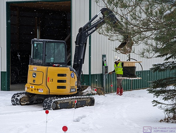
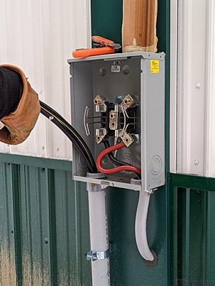
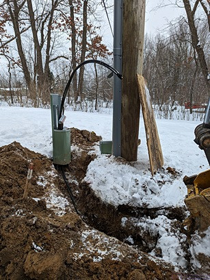
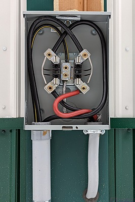
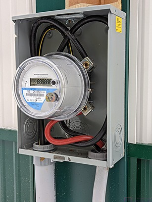
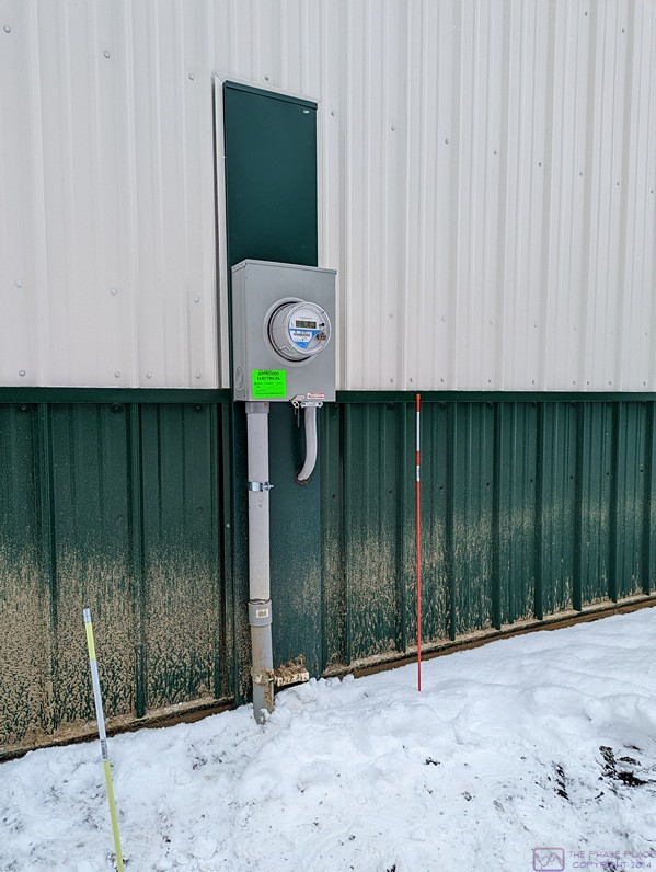
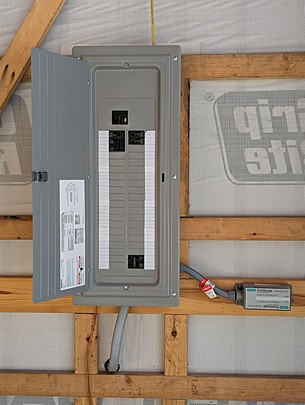
As November gave way to December, it became clear that we had reached the stage in this project where sayings such as “the last 10% of a project takes 50% of the time” always seem to come into play.  Not labor hours, of course, but calendar time, and visible milestones, for sure.  The building is constructed; the electrical service entrance (meter enclosure, main panel, and outlet/receptacle) is installed, inspected, and approved; and the driveway is finished (for now).  Separate from the building contract, the 2” Schedule 40 PVC electrical conduit has been trenched in from the meter enclosure to near the existing utility pole.  Other than wiring the building, which is on me to do, it looks/feels like we are very near completion of the builder’s portion of the project, but big things remain to be done.

FRIDAY 02 December

Chuck, the builder, let me know that he had finally gotten an estimated availability date from the vendor for the two large roll-up doors … December 28th (of this year).  There is always a list of a few minor things that need to be done or corrected, but these doors are one of the two remaining major components of the actual building construction, the other being the gutters.  At this point, I presumed that they would not be installed until early in the New Year.  Work on this project started in the second half of June, not long after we left for our 4-month journey through Eastern/Atlantic Canada, so mid-January would mark the seven (7) months point.

TUESDAY 06 December

Today was a big day; we finally received the costs to have the electric power on our property upgraded and extended to the new accessory building (RV barn, workshop, storeroom).  Also, sometime today (or yesterday) the gutter sub-contractor was apparently here and installed the gutters and downspouts on the two long sides of the barn.

WEDNESDAY 07 December

Today was, perhaps, an even bigger day than yesterday, as I finally received the actual contract for the electric utility work.  All that remained to do was read it carefully, sign it, scan the pages, and e-mail them back to a special e-mail address at DTE Energy.  I looked the contract over, especially the costs.  The language used throughout the documents was specialized for DTE’s purposes, but I had a sense of what was what, and everything appeared to be in order.  I was missing a diagram that the cover letter said I was supposed to have, and had a few other procedural questions, so I e-mailed our DTE planning consultant back.

The most expeditious way to move things along was to scan the signed documents and e-mail them back.  This would trigger a reply e-mail with a link to a special payment website.  I decided to hold off submitting everything until tomorrow so I could read all of the boilerplate contract language.

The way the project was now moving, and with real winter just around the corner, it appeared that I might not get any wiring done in the barn until spring.  Since I would have time between now and then, I had been considering purchasing the 2023 version of the NFPA 70 / NEC (National Electric Code) Handbook, which will be available on December 15, 2022.  It’s a bit spendy, but the Handbook contains the complete text of the CODE along with extensive inline commentary, diagrams, and photos that “explain/illustrate” what the CODE language means, and how it is applied in practice.  That sounded like some interesting and meaningful “home study” over the early winter months.

The builder was here today to see what was wrong with the shop and storeroom doors, and fix them if possible.  Before looking at the doors, we were both surprised to see that the gutters had been installed (on the long sides of the building).

Both doors are very difficult to open, and both of them have dead-bolts that will not slip into their strike plates, even with jiggy-jogging them.  Chuck determined that the difficulty in opening was due to bottom sweeps that were a bit too thick, although they might become a bit more compliant with use and age.  The sweeps snap in and out fairly easily, and he will try to get slightly thinner replacements for both of them.

The storeroom door appeared to be installed correctly, with an even reveal between the door and the frame on the inside and with everything square.  The solution for the dead-bolt will be to grind the strike plate, which is OK with me.  (It’s what I would have done if I was fixing it.)  He would have to come back to do that.

The Shop door, however, was not installed correctly, being slightly out of square and not having an even reveal between the door and the frame from the inside.  Chuck said he would be out in the next few days to remove it and reinstall it, or have one of his carpenters do it.  It’s already trimmed out, so I don’t know if that means removing and reinstalling all of the trim, but he said it was the only correct way to fix the problem.

THURSDAY 08 December

Linda had to go into the bakery today, so during the first part of the morning I read over the entire DTE contract package.  I then signed it in the two places that I needed to, and scanned those two sheets, saving them as PDFs and renaming them for clarity of content.  One was the “Line Extension Agreement” and the other was the “Secondary Services Agreement.”  I attached both PDFs to an e-mail and provided additional contact information per the information from my DTE planning consultant, and sent the e-mail off to the special DTE e-mail address.  I wasn’t sure how long it would take for DTE to respond, so I left to run some errands.

While I was out, I got a text message with the payment link.  So far, so good.  When I got home, I also had an e-mail with the payment amount.  But I had a second e-mail indicating that I had not submitted all of the required documentation.  I spent the second half of the afternoon scanning the rest of the pages into PDFs, renaming them, attaching them to an e-mail (along with some additional information), and sending it off to the special DTE e-mail address.  By then, it was late enough in the day that I was tired of dealing with this and ready to sit on the sofa and work a puzzle or watch a Youtube video while I waited for Linda to get home.

After an easy dinner of salad and pizza, Linda used the payment link and paid the invoice.  Correct documents or not, they were more than happy to accept our money (CC).

I will check e-mail tomorrow morning to see if I got it right on the 2nd try.

FRIDAY 09 December – WEDNESDAY 14 December

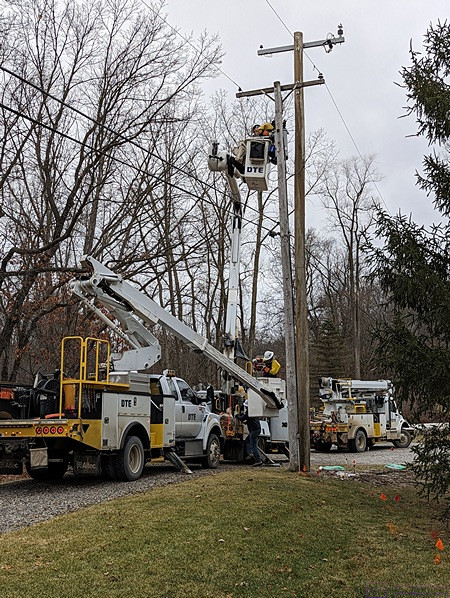
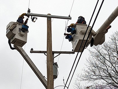
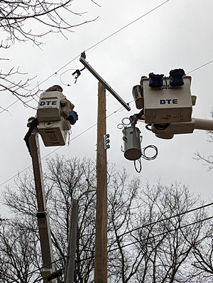
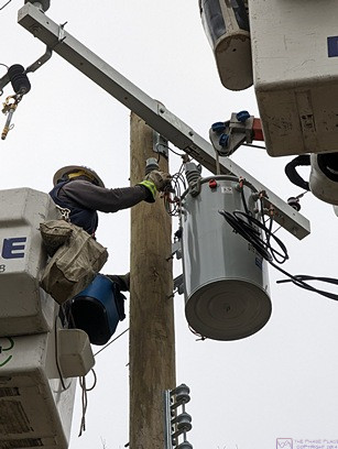
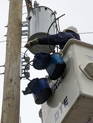
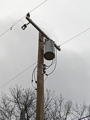
Well, the contract was accepted as complete and we received verification that our payment had been received.  I contacted our DTE planning consultant to let him know.  He replied back that it might take a couple of days for him to receive official/internal confirmation, at which point he would generate the work orders needed for the project.  That internal communication eventually took place, at which point I was notified that the work would “probably” be completed by the end of January, but not later than 17 February (2023).  That was discouraging to hear, but this was the first time I had dealt with DTE on a project like this, so I was not familiar with all of the steps or the timelines involved.  Regardless, it was out of my control.

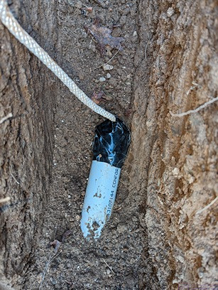
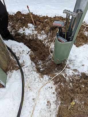
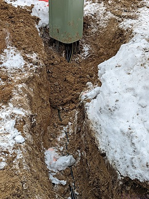
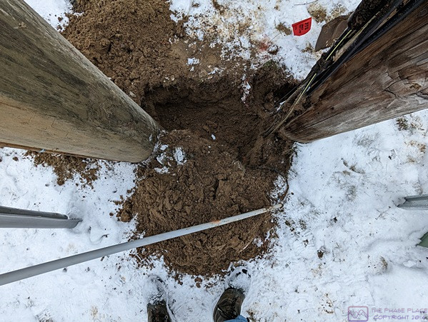
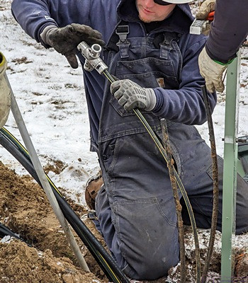
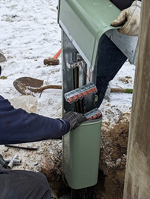
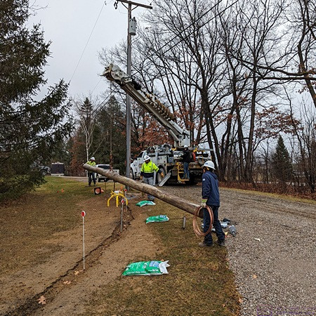
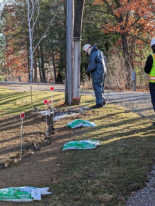
The free end of the conduit near the utility pole with the 7/16″ rope passed through the hole in the end cap and everything taped to prevent dirt and water intrusion.

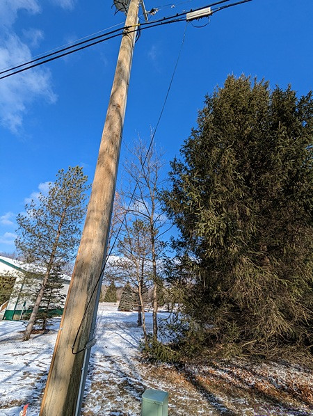
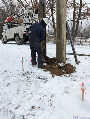
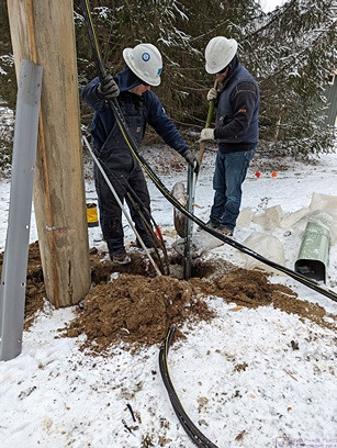
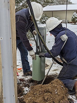
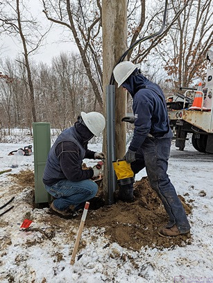
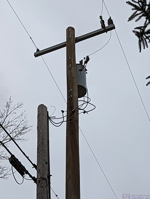
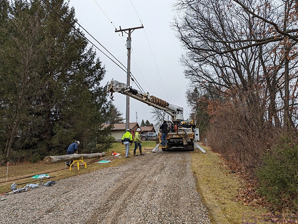
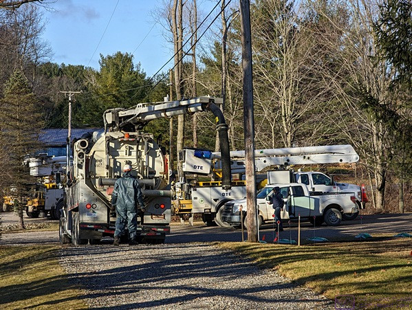
Sometime prior to the 14th, the DTE planning consultant made another site visit to have a second look at the utility pole replacement and the conduit we had installed from the pole to the barn.  Because the conduit runs downhill from the pole location to the meter location, he suggested I try to seal up the open end by the conduit as best I could to prevent water/dirt from getting in.  Given the time of year, if water got into the conduit and froze it would prevent the cables from being pulled through and we would have to wait until the spring thaw to get the service conductors installed from the pole to the barn.  He also marked the location for the ground pedestal (junction box), but indicated that the crew(s) that did the work might place it in a slightly different location.


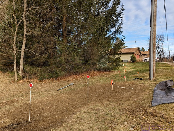
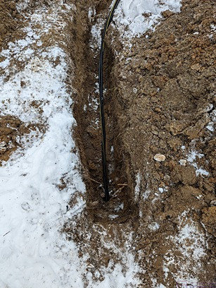
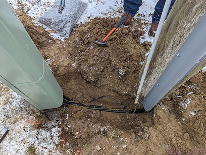
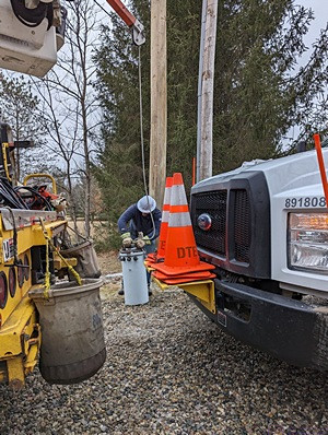
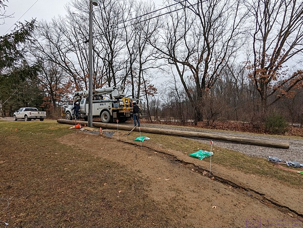
A view of part of the trench, filled in and raked out.

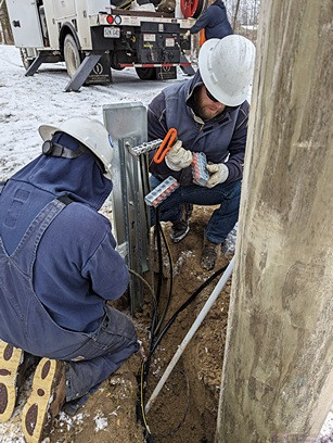
Marty and I had placed a 7/16” rope in the conduit after we assembled it and put it in the trench.  One end was tied around the lugs in the meter can, and the other end came out the open end of the conduit and up a wooden stake marking the end of the conduit, as we planned to bury it, where it was tied at the top so the end could be easily located later.  I had tried to seal the open end with a rag, but this was not adequate.  I had a cap with a domed end, so I drilled a 1/2” hole in the end of it, fed the rope through the hole, and slid the cap over the end of the conduit.  Although not glued, it was a snug fit.  I taped around the rope at the hole, and around the cap and conduit with Gorilla tape.  I retired the rope to the wooden stake, and then buried everything.

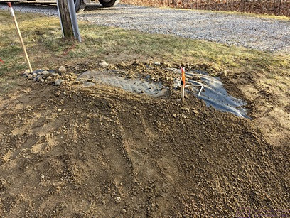
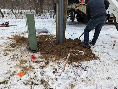
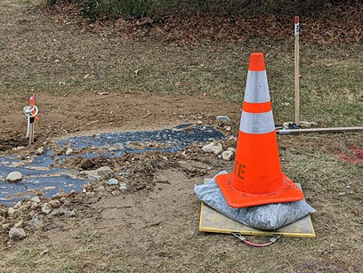
The trench beyond the free end of the conduit has been back filled and marked with a stake that secures the rope. Plywood has been put down and covered with plastic and dirt to keep as much water out as possible.


THURSDAY 15 December – SATURDAY 31 December

With the holidays coming, and a trip planned between Christmas and early January, not much else happened on this project the rest of the month.  The builder was notified that the roll-up doors were now delayed until the end of January, 2023.  Oh well.  Again; out of our (and his) control.