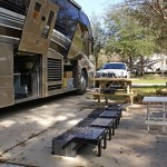
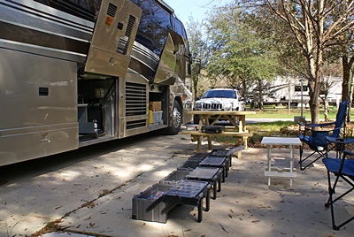
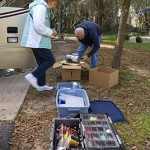
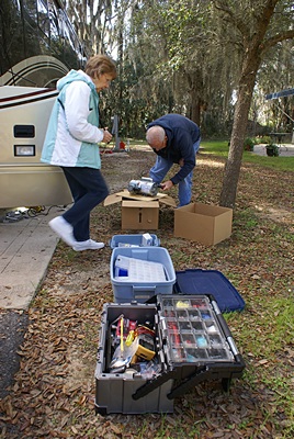
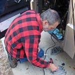
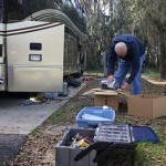
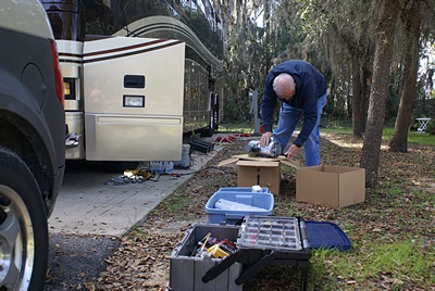
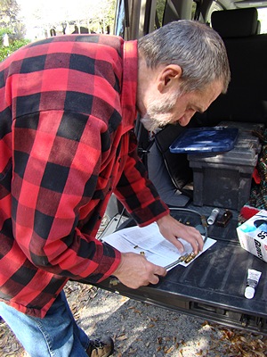
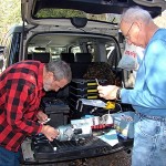
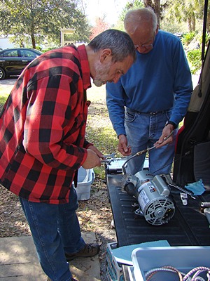
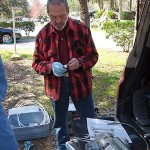
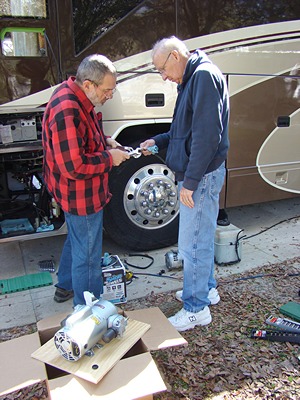
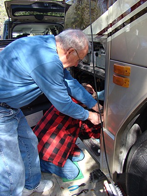
John and Marian arrived at 10 AM as I was getting ready to unload all of my tools and materials from their storage locations. Marian brought her camera and took pictures of us working and I took photos of the details of the work as it progressed. I have placed the photos in a separate gallery post with today’s date.
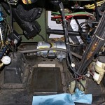
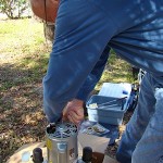
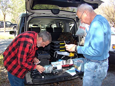
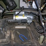
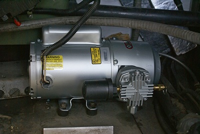
We looked at the old compressor and figured out what we had to do to remove it. The auxiliary air compressor is mounted to the floor of the bay under the driver’s seat. It is not a large bay, but it is big enough to allow access to the things that are installed there, especially after the plastic 5 gallon windshield washer fluid tank is removed. (Yes, it holds 5 gallons of washer fluid; it’s a bus and everything on it is super-sized.)
I tried applying AC power to the compressor one last time with zero pressure in the auxiliary air system, but it was still seized. I shut the circuit breaker off so we could work safely on the electrical aspects of the project.
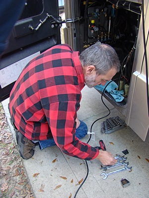
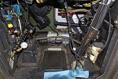
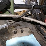
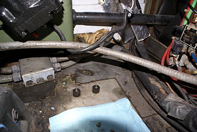
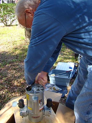
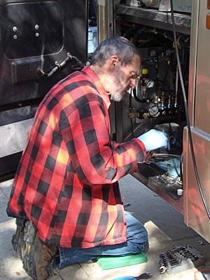
With the washer fluid tank out of the way we could see that the compressor was mounted on four rubber isolation mounts. These mounts were ~1″ thick with bolts protruding from either end. One end was bolted to the air compressor mounting flange. The other end went through a hole in the floor and was secured with a Nylok nut from under the bus. The compressor was installed with the length oriented front-to-rear (buswise) so we could get to the interior nuts on the side of the compressor facing us, but not the ones on the other side. We could hardly see those nuts even with the inspection mirror. Fortunately the bottom bolts were close enough to both the driver side and front of the bus that I could reach them without having to get under the bus. With the auxiliary air system bled completely down the suspension was holding, so we did not put the bus up on stands for this work. I do not get under the bus under those conditions.
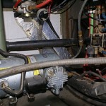
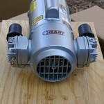
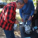
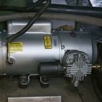
We disconnected the air line from the compressor while it was still mounted and then disconnected the other end from the T-fitting and removed it from the bay. We then unbolted the air compressor and turned it 90 degrees so we could get to the electrical connections on the end of the motor. With the electrical connections undone we were able to lift the old unit out. It weighed about 30 pounds.
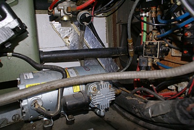
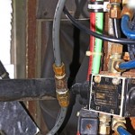
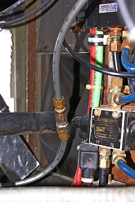
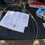
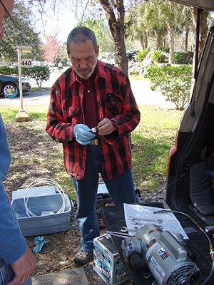
Butch had alerted me to the possibility that the check valve I bought from Prevost might not be exactly what I need. He said that air compressors usual have an unloader valve or mechanism in the air line ahead of the check valve. The purpose of the unloader mechanism is to bleed the pressure off of the air pump when it stops running so the next tine it starts it is initially working against zero pressure. We examined the old check valve and sure enough, it had an “extra” piece with a small port in the side. We tested it and verified that the check valve was, in fact, leaking but the pressure relief valve was working. We also discovered that all of the fittings were compression rather than pipe thread like my new check valve.
After studying the situation for a while John and I agreed that the best course of action was to reuse the old check valve and unloader and put the new check valve in the air line downstream from them. The new check valve would prevent backflow to the new auxiliary air compressor, and protect it from the higher pressures generated by huge main engine air compressor, while the unloader would relieve the pressure on the auxiliary air pump when it stopped running.
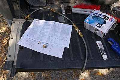
This was the point at which we realized that I did not have all of the necessary fittings to reassemble the air line with the new components. John got on his phone and found that there was a NAPA auto store not far from the RV Resort. It’s always something. This is why jobs that should only take “a few hours” end up taking all day (or longer). Two trips later and we had everything we needed.
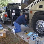
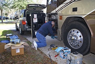
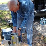
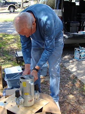
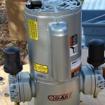
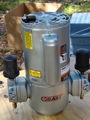
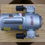
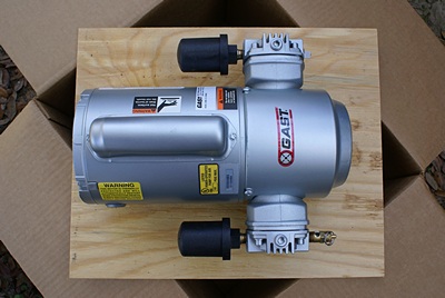
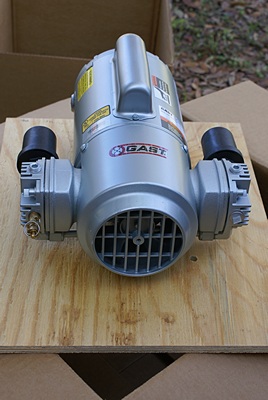
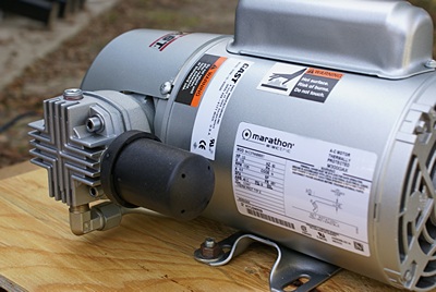
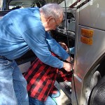
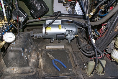
We assembled the air line in two pieces using old and new fittings. We used PTFE pipe thread compound on all of the threads. As I do not travel with a vise it was very helpful having four hands to hold things and another pair (Marian) to help as needed. (Our mechanic would like me to mount a vise to trailer hitch so I can slide it into the receiver on the back of the bus or the car. That would have been handy for this project.) We attached one piece of the air line to the compressor and the other piece to the T-fitting. John had previously attached the two isolation mounts that came out with the old compressor. We set the new compressor in the compartment with the motor pointing out and reconnected the AC electrical power. We then turned the compressor 90 degrees and dropped the rear mounting bolts through the two holes in the floor. John had put the mounts in just the right place and it was a perfect fit! We put all the nuts on and snugged them up. The final step was to join the two pieces of the air line together and test it.
I turned on the AC power and it purred like a kitten. Well, maybe like a really big, loud cat. We watched the pressure gauge in the auxiliary air manifold and although we could hear air being pumped the pressure was not coming up. I quickly realized that the primary and secondary tanks had bled down to about 40 PSI and the auxiliary air compressor had to fill them to 70 PSI before the auxiliary air tank/system would fill. The auxiliary air compressor is not intended to fill the entire chassis system, although it does maintain the pressure at its cut-out setting, so I shut it off.
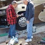
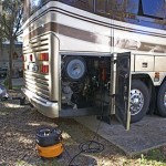
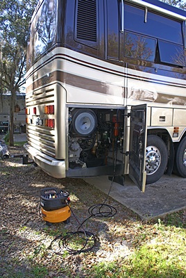
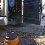
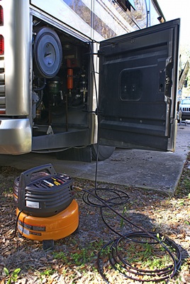
I had asked John to bring his portable air compressor and he did. We connected it to the fill connector/valve back by the main engine and used it to fill the primary, secondary, and auxiliary air systems to about 110 PSI. I then turned the power back on for the auxiliary air compressor and opened the drain valve on the auxiliary air tank. At 80 PSI the auxiliary air compressor came on. I shut the drain valve and the pressure came back up to about 104 PSI. The system was back in operation! I started the stopwatch on my smartphone to time how long it would take to leak down to the cut-in pressure while I cleaned up and put away tools.
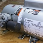
The only issue at this point was that the auxiliary air compressor was rated for 100 PSI maximum pressure so the pressure control switch needed to be adjusted. I turned the power off, removed the cover from the pressure switch, and discovered that it had three spring-loaded adjustments rather than the two I expected to see. I put the cover back on, restored the power, and suggested that the three of us go out to dinner at Angelina Mia.
At the restaurant I made a special request for pasta in olive oil. The owner was there and she came to the table to clarify what I wanted. She said she could do spaghetti with olive oil, garlic, some hot pepper flakes, and spinach. Winner! I also found out that Angelina and Mia are her daughter’s names. We did not get around to working on dashboard wiring issues today, so John and Marian agreed to come back tomorrow.
After dinner I got online to research how to adjust the pressure switch, but everything I found was for a unit with two adjustments, not three. The key, however, was that the diagram for the unit was probably inside the cover. I had not thought to look there earlier. That would be the first task for tomorrow, and then on to wiring issues.