[ Note: This post mainly consists of 26 photos with captions. All of them were taken on a Google Pixel 6 Pro smartphone and processed using Faststone Image Viewer. ]
TUESDAY 15 November – WEDNESDAY 30 November
As previously noted, the electrical service entrance was prepared on Thursday, November 10. By this time, the weather was changing, becoming cold enough that I could no longer paint. Any painting that remained to be done, such as the outside of the two interior shop/storeroom walls, and the sides of the staircase, would have to wait until spring 2023. With my painting activities curtailed for the winter, and with the electrical service entrance work done, I turned my time and attention to designing the electrical plan for the building using QCAD. Indeed, I started with the building floor plan, turned off details that were not relevant, and added new layers for all of the electrical stuff. Outlets, switches, a sub-panel for the shop/storeroom, and wiring would be fairly straight forward; it was just a matter of how many devices, where they would be placed, and how/where the wires would be run. Lighting, on the other hand, lead me down something of a rabbit hole researching lighting requirements and fixtures.
With a 16’ clearance to the bottom of the roof trusses, I need to use “high bay” light fixtures for the RV bays. These fixtures are much brighter (8,000 to 35,000 lumens) than the typical “shop/utility” tube lights used in many residential garages and workshops (2,000 to 4,500 lumens). Selecting fixtures that will work the way I need them to, required me to jump back into lighting parameters such as illumination (in lumens), color temperature (in degrees Kelvin), Color Rendition Index (CRI), beam patterns and coverage (as a function of height above the working surface), mounting/wiring methods, suitability for use in unconditioned spaces (the RV bays), and energy efficiency. The last one was easy, as all of the lighting that I install will be LED, which has a 10:1 energy advantage over tungsten filament bulbs. (LEDs use ~1/10 the energy of a tungsten light source for the same amount of illumination, or provide 10x the amount of illumination for a given energy consumption.) LEDs also have a lifespan that is 10 to 50 times that of tungsten bulbs, and come in a variety of color temperatures, specifically 5,000 K (Daylight) which is appropriate for areas where work is being done. A comparison to fluorescent lighting would probably be more appropriate, but LEDs still come our way ahead on all of these parameters. I will have more to say on this subject once I have actually selected light sources.
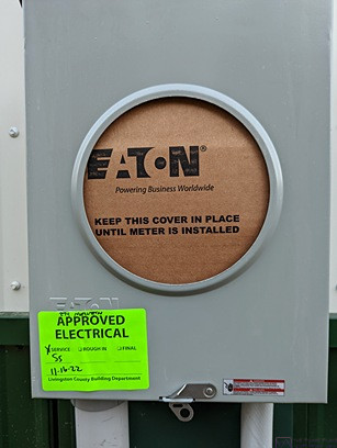
The electrical service work (meter box, load center, and one duplex outlet) was inspected and approved on Wednesday, November 16. This was a critical milestone in the project, as DTE Energy won’t do anything relative to getting power to the building unless/until this work is completed, inspected, and approved. I e-mailed the DTE planning consultant (John B.) late in the evening to let him know this work was done. Following this approval, I purchased the 2” Schedule 40 PVC electrical conduit and couplers from City Electric Supply in Waterford, Michigan. They did not have the sweeps I needed, or the 22.5-degree elbows. I found the sweeps at Lowe’s and/or Home Depot, but had to order the 22.5-degree elbows online (Amazon).
MONDAY 21 November
In spite of the cold weather, and 4” – 5” of snow on the ground, there was work that had to be done. On the couple of occasions when it had snowed prior to today, I used a gasoline powered backpack leaf-blower to remove the snow from the electrical cable paths from the existing utility pole to the house (which had been marked by MISS DIG 811) and the area from the pole to the barn where I intended to dig a trench and install the conduit for the electric service entrance cable.
I had a few errands to run today, and when I returned I found two DTE subcontractor trucks parked in the street in front of our house, with one of them blocking the first driveway entrance. That wasn’t a problem, as the bus is currently parked in front of the house and I had no immediate use for the first entrance. Still, I was curious why they were there so I walked over and talked to the guy in the lead truck.
They had spent the morning working at our neighbor’s house across the street. Our neighbors are the third owners of the first house built in this subdivision. Built in the late 1960’s, the house still had its original 240/120V, 100A electrical service. They are upgrading it to 200A, and that meant a new main panel, a new meter/box, a new transformer, and new cable from the pole to meter. Their existing service was overhead wires from the pole to the house, but DTE will not upgrade those wires. As with new construction (like our barn), they will only run cable underground from the pole/transformer to the meter on the side of building. They also install a terminal strip on the pole a few feet below the transformer and connect the wires from the house and the transformer together at the terminal strip. These particular sub-contractors where an “underground” crew and had spent the morning digging a trench from the pole to the meter location, installing direct-burial cable, leaving enough of it coiled up on a hangar on the pole to reach the terminal strip, and then back-filling the trench. A DTE crew will come out and remove the old overhead cable and transformer, mount the new transformer and terminal strip, route the new cable up the pole, and make all of the connections.
The sub-contractors were on a break, and I asked if the guy would be willing to take a few minutes to look at my situation. The thing that has been a source of confusion for me was where to end the trench/conduit, and what direction it should be pointed. My DTE planning consultant had simply indicated “about 10’ from the existing pole.” But that lacked the specificity that I wanted as we were (apparently) also getting a new/taller utility pole that would (probably) be installed “about 5’ to either side of the existing pole.” It would, of course, be in line with the existing overhead cables (power, broadband, and phone). I knew that DTE would also install a ground mounted junction box/pedestal and that the wires from the house, barn, and transformer would be joined in this box. But it was not clear exactly where the pedestal would be placed relative to the existing pole, much less the new pole in an as yet undetermined location. My confusion/concern was also partly fueled by not having ever dealt with this before and not understanding exactly what was actually going to happen.
The sub-contractor looked at my proposed path and filled in a few critical pieces of missing information. I learned that the junction box would (likely) be installed about 3’ from the new pole, directly away from the edge of the driveway. If I located the end of the conduit in-line with a line offset from the existing pole by 3’, and stopped a few feet short of the possible closer junction box location, it would be a perfect setup for a crew (like his) to do what they need to do. I also learned that they will NOT install additional conduit from my conduit to the junction box; all the cable they use is rated for “direct-burial” and does not actually require conduit. (Conduit is nice, however, especially in rocky soil or other situations where it might be subject to damage.) They will simply trench from the end of my conduit to the junction box/pedestal location, as well as from the pedestal location to the new pole location. Finally, he assured me that I would not have any difficult bending the 2” Schedule 40 conduit along my indicated path. Based on what I learned, I staked out the actual path for the trench/conduit from the barn to near the existing utility pole, using landscape flags.
TUESDAY 22 November
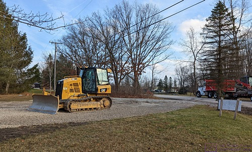
Today was spent digging a trench and installing approximately 90 feet of 2” Schedule 40 PVC electrical conduit, including a 36” radius sweep (quarter circle) and a 12” long 22.5 deg elbow. The conduit will house the service entrance cables that the power company will run from the pole to the building.
My friend and fellow converted bus owner, Marty, who is a licensed electrician, agreed to come over and help with this task. I was glad to have the help. The work proved to be quite physical, and often required coordinated effort; I doubt that I could have accomplished it by myself. Linda also helped, off and on throughout the day, taking breaks from her accounting work to take photos, fetch things that we needed from the garage, fixing a light lunch, and taking on the task of cleaning the rented trencher with our power washer once we were done digging. (We had chosen this day to do the work because the high temperature was going to be well up in to the 40’s.)
But before that happened, I used yellow marker paint (spray can designed to work when inverted) and “painted” the path that I had marked with flags yesterday. I then unloaded the 36” trencher from the trailer as I wanted to be ready to work as soon as Marty arrived around 9 AM.
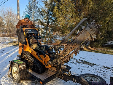
On Monday evening, November 21, I rented a 36” trencher from the local Home Depot for 24 hours. This would allow us to use the machine all day and still be able to clean it and return it on time. (The 24-hour rental was only 22% more than the 4-hour rental.) This particular machine digs a trench approximately 5-1/2” wide. This photo is from 8:30 in the morning as I prepare to back the trencher off of the tilt-bed trailer, which was part of the rental. The machine was chained down to the trailer for transport. The only issue I had was releasing the tension on the front chain, but I eventually figured out how to loosen it. (Photo by Linda.)
I had never operated a piece of equipment like this, but last night I studied the directions that came with it, and it seemed straight forward enough. In this photo, I have backed the trencher up enough to cause the trailer bed to tilt down and touch the ground so I could back the trencher off onto the driveway. (Photo by Linda.)
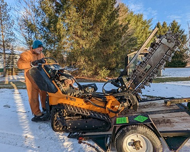
Marty and I decided to dig the trench for the conduit starting at the meter and working towards the utility pole. In this photo, I am driving the trencher over to the meter box location. Although not obvious from these photos, the overnight low temperature was in the low 20s (F) and the ground was initial quite firm. It was not deeply frozen, however, and was easily dug. By late morning the temperature had risen above freezing and we had a clear sky with a bright sun. All of the areas of bare dirt (not grass) within a 15-foot radius of the meter box turned to mud, which only got worse as the day went on, with a high temperature in the low 40s (F). (Photo by Linda.)
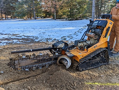
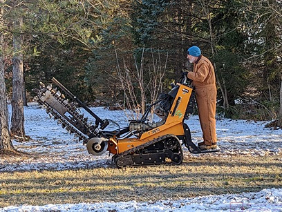
When digging, the trencher is driven backwards. The operator stands on the platform at the rear and can see the digging chain when it is raised, but cannot see it when it is lowered. I’ve just dug a short section of trench coming out from the riser conduit into the meter box, and have lifted the chain out of the ground. Where the chain meets the body of the trencher (yellow) a horizontal auger is just visible. When digging, the auger moves all of the dirt off to the left (when facing forward). Visible on the safety bar above the blade is a piece of white tape. It was already there when I picked up the machine, but turned out to correspond to an ~27’ trench depth, which is what we were aiming for. DTE Energy requires the top of the conduit to be at least 24” below grade. (Photo by Linda.)
I did not get a photo of the control panel, but it consisted of a choke and throttle for the engine, a control lever to lower/raise the blade, two drive controls for the left and right drive treads (like a bulldozer), and a lever to engage/disengage the chain. The engagement lever moved sideways, and had to be pulled over with my right hand and held there while also operating the right drive tread. It was actually easier than it sounds, and I got the hang of operating this beast fairly quickly.
Marty spots me to get the tip of the blade as close as possible to the riser conduit into the meter box, and let me know when the blade was at the correct depth. (When the blade was lowered and digging, I could not see any of it, including the piece of white tape that served as our depth gauge.) Because the trencher is driven backwards while digging, I was able to see the yellow stripe (about 2” wide) through the operator platform, which was perforated and ridged for good traction. (Photo by Linda.)
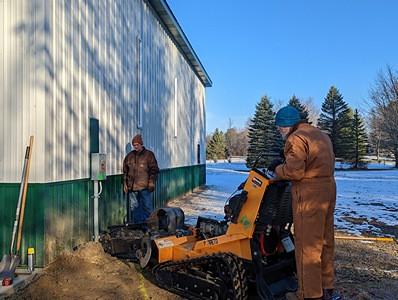
Conduit assembly started at the meter box end. I held a 36” radius sweep against the riser conduit into the meter box with the other end at the bottom of the trench while Marty marked the point where we needed to cut the riser so we could join it to the sweep. The upper portion of the riser had a threaded fitting already installed into the meter box. A nut inside the meter box threaded onto the fitting to secure the riser to the box. (We set the lower portion of the riser aside after cutting it, and eventually used it as the last piece of conduit at the pole end.) In this photo, we are adding a 22.5 deg elbow to the end of the sweep. I held one end of the sweep against the side of the barn so that it was parallel (vertical) while the other end rested on the concrete apron (horizontal) and Marty loosely fit them together and marked them at the position where the elbow was flat on the concrete and bending in the correct direction. We then lay the pieces down on the apron for assembly. We could not trench in a direct line from the meter box to the pole because of several trees, but the combination of the sweep and the elbow got the conduit pointed in the direction of the straight portion of the trench. Part of the trench is visible behind Marty.
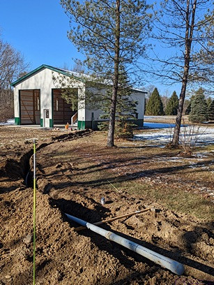
This is a view of the trench from near the existing utility pole. (This pole will be replaced with a taller one located within 5 feet either side of the existing one.) The end of the conduit is propped up above the trench so we can add an additional piece to it. The first 30’ (approx.) after the sweep/elbow is straight and angled away from the trees. It then curves around the trees in a broad sweep. At the pole end, the conduit is running approximately parallel to the edge of the driveway and about 3 feet farther away than the pole.
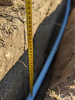
DTE requires a minimum depth of 24” from grade to the top of the conduit. This photo shows that we are at 27” (the trench depth varied from 27” to 30”). A single piece of this 2” Schedule 40 PVC conduit does not appear to be at all bendable. However, the DTE contractor that was here yesterday assured me that a longer run would bend just fine for the curve I had marked out. We added two 10’ pieces (“sticks”) at a time, and then pulled it around into the trench with no difficulty, keeping the free end out of the trench and resting it on a shovel handle set across the ditch so we could install the next piece(s).
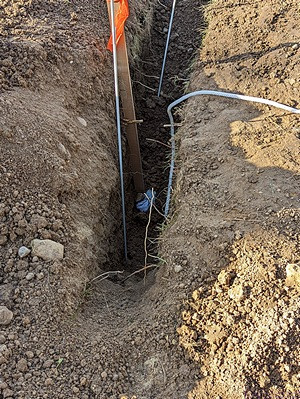
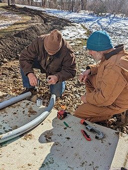
This is the utility pole end of the trench/conduit. The stake marks the end of the conduit. We used a 125’ steel “fish tape” to pull a 100 foot, 7/16” rope through the conduit from the pole end and into the meter box. (This rope has a 300 lb. pull strength.) Marty handled the meter box end while I fed the rope into the conduit. There was approximately 4 feet of rope at the meter box, which Marty wrapped around the meter socket before putting the cover back on. I had about 6 feet of rope at the pole end, which is just visible in the lower right corner of the photo. The white object in the trench is a cotton rag that I stuffed into the end of the conduit to keep dirt out. The end of the conduit is about 6 feet from the existing utility pole (5’ to the west and 3’ to the north. Everything after this will be done by DTE or their sub-contractors.
WEDNESDAY 23 November to MONDAY 28 November
I was sick with an upper respiratory viral infection during this time (and beyond), and nothing else much was accomplished on the barn. I did learn on Monday that the ETA for the two large roll-up doors is now December 28 (of this year). I also emailed our DTE planning consultant to let him know the conduit was installed in the trench and included pictures, as requested. He indicated that he would (finally) do our plan/quote on Monday, November 28. On Monday, I also heard from Phil at Precision Grading that he would have the 21aa stone delivered tomorrow and be on site to finish the west pull-through driveway extension to the barn.
TUESDAY 29 November
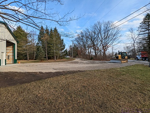
Phil arrived around 10 AM. He got his front-loader and bulldozer unloaded from his equipment trailer and then unloaded a large roll of road/construction fabric from the box of his dump truck using forks on the front-loader. I made myself available to help with placing the road/construction fabric, but otherwise spent most of the day cleaning up the dirt along both sides of the conduit trench. This included gathering up medium-to-large rocks and using them as fill for the somewhat larger hole near the meter and along the first 5’ of the trench. I took occasional breaks to take photos of the driveway work. We both finished up around 4:30 PM. It was a long, hard day, but a lot got accomplished.
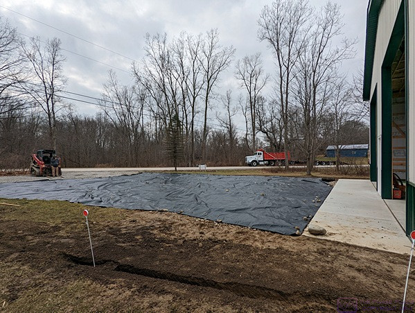
This is a view looking SW from the SE corner of the bar showing the first pieces of road fabric in place on the “1×3” stone and crushed concrete base layer. Phil is standing in front of the front loader at the left of the photo. His dump truck and equipment trailer are in the street. The bulldozer is barely visible at the far corner of the barn.
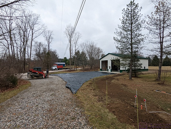
This is a view looking W from near the existing utility pole at the edge of the existing west pull-through driveway. The area covered by the road fabric is the new driveway extension/approach for the barn. This is where most of the new gravel will be placed. This new area will slope down to the SW, away from the barn and from the yard to the right in this photo. (Note that the yard to the right will drain to the NW and surface water will flow N along the east side of the barn and then flow W past the rear of the barn. Phil had previously graded the area around the barn, but will return at some point to add soil and regrade this area to ensure proper drainage.)
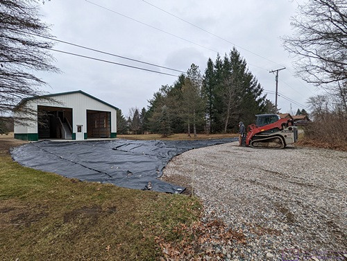
This is a view looking NE from the SW corner of the existing pull-through driveway. The curved edge of the new area to the left is to accommodate the left steer tire of the bus when swinging around from the pull-through driveway to pull into the left RV bay.
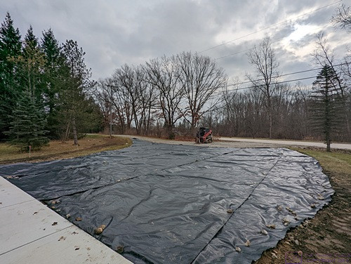
This is a view looking SE from the SW corner of the barn. The pull-through driveway slopes down from just before the existing utility pole all the way to the street. The yard on the other side of the new driveway extension slopes towards the camera and to the left. The new driveway extension slopes away from the barn and away from the yard to the right and down towards the street.
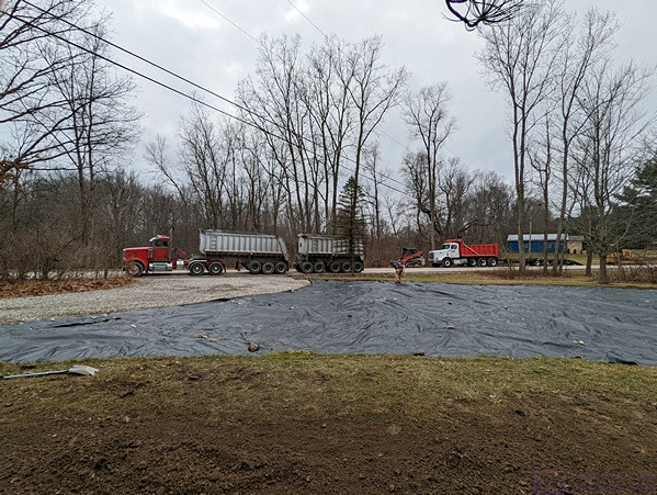
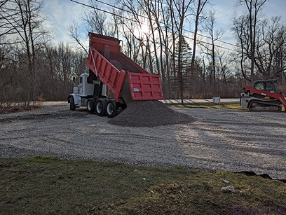
This is a view looking SW as the gravel train prepares to back into the driveway and dump the gravel from the rear trailer. Phil will help the driver get it positioned so that the gravel pile is mostly on the road fabric.
The first load of stone has been dumped and the truck is pulling out while lowering the trailer box. The driver pulled to the far side of the street and then unhooked the rear trailer so he could back in and dump the main truck box.
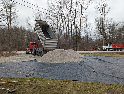
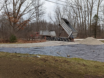
This is the second load of stone and is being dumped from the actual dump truck. The two piles of gravel visible here contain a lot more gravel that it might appear (approximately 20 cubic yards, or about 60,000 pounds).
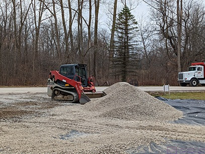
In this photo, Phil is using the front loader to scoop up the gravel and move it to various locations on the road fabric.
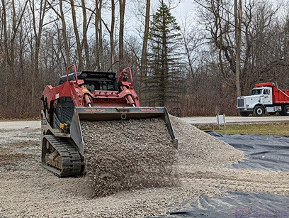
Here, Phil is using the front-loader to deposit/spread the 21aa stone.
Phil needed more stone to finish the job. He had some at his shop, which isn’t too far from our property, so he dropped his equipment trailer and took his dump truck to get it. His stone is darker than what was delivered earlier, due to being a bit wet.
Once all of the gravel was placed and spread somewhat evenly, Phil switched to the bulldozer to grade it.
Besides getting a relatively flat surface and consistent thickness, Phil used the bulldozer to carefully grade the stone along the edges. The bulldozer is very heavy, so it also created some compaction of the stone.
Buy the end of the day, the new driveway extension was a surface that could be driven on comfortably, but was not as compacted as I wanted it to be. In the next few days, I would use the F-150 to drive back and worth over the gravel from a variety of directions to pack the surface, but that’s for a future post.
WEDNESDAY 30 November
One of the carpenters from Patriot Builders was here today to install the locking door knobs and deadbolts for the entry, shop, and storeroom doors. The three door knobs and two deadbolts (shop and storeroom) were all keyed alike.
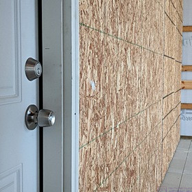
Exterior view of the shop door with the locking door knob and deadbolt installed.
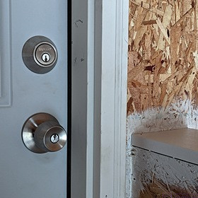
Exterior view of the storeroom door with the locking door knob and deadbolt installed.
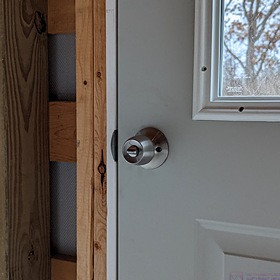
Interior side of the entry door with the locking door knob installed. Besides the window, this door has deeper jams to match the thickness of the wall, protruding 1/2” into the interior to accommodate drywall or plywood, should we wish to add that in the future.
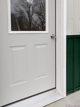
The exterior side of the entry door with the locking door knob installed. This slightly broader view shows the panel detailing on the lower portion of the door and a bit more of the window.
…