We had not been to our local ham radio club breakfast the last two Saturdays because of the GLAMARAMA rally and a visit from Linda’s brother, Ron, and his wife, Mary. The club was conducting VE testing today, rather than the usual 4th Saturday of the month, because the ARRL Field Day event is next weekend. When we got to breakfast at 8 AM there were already a lot of people there and seven more came in after us. We did not take a head count but it was somewhere between 25 and 30 people. We also did not have our usual waitress but the substitute very efficiently got everyone’s order taken and delivered.
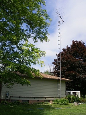
The 40 foot tower on the east end of the house with the old OTA TV antenna on top.
I checked with Mike (W8XH) and he is available to help us get the antennas mounted on the small tower on Monday or Wednesday, assuming I have the cable entry box (CEB) installed and all of the necessary coaxial cable on hand. Getting the CEB mounted was my main goal for today, but not the first thing I had to do. I called Chuck as we were leaving breakfast at 9:15 AM. He was at home and suggested we stop by there and pick up a key to his shop. He was working on landscaping when we arrived so we did not stay long and we were back home by 10 AM. Linda finalized her shopping list and headed off to gather the things she needed to prepare tomorrow’s brunch. I changed into my work clothes, gathered up the laundry, put a load in the washer, and got to work on the CEB.
The CEB is designed to mount on the outside of the house, allowing wiring to pass between the inside and outside of the house in a way that is weather tight and animal proof. Coaxial RF cables and control lines enter through the bottom, connect to lightning arrestors in the CEB that provide a path to ground if/when needed, and then continue through the wall of the house and thence to various devices. Those devices might include cellular phone signal boosters, Wi-Fi systems, TV sets, satellite receivers, personal weather stations, or amateur radio gear such as radios, remote antenna switches, and antenna rotators.
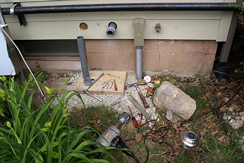
The general area on the east end of the house at the base of he 40′ tower where the CEB will be mounted.
Superficially the installation looked simple. With the copper back plane removed there were four mounting holes, one near each corner, and two large holes in the back. All we had to do was hold the box against the wall, mark the locations of the four mounting holes and the big cable entry holes, set the box aside, drill the holes, put the box back up and secure it. Right. Sort of, but not exactly. Mounting the box took seven hours to complete.
The first step was to remove the copper back plane with the three lightning arrestors installed on it. I took care of that yesterday. The next issue was that the house has shiplap siding, i.e., the east wall where I needed to mount the CEB was not a flat surface. I decided to use 1″ square aluminum tube, installed vertically along the back of the box at the outside edges, to span multiple siding boards, ensuring that the CEB would be plumb. I also decided to leave the tube long enough to go all the way to the ground and use it to support some the weight, in effect creating legs for the CEB. That was Linda’s idea. She’s a smart girl and a licensed amateur radio operator.
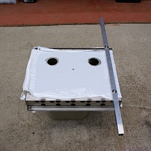
The back of the CEB with one of the vertical mounting bars.
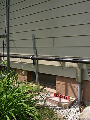
We had some surplus pavers and garden blocks and I found one that was just wide enough to catch the bottom of the legs. I also had some left over paver base material, which meant I did not need to make a trip to the store. The paver base material was from a project long, long ago (in a place far, far away) and I used it to create a base for the foundation paver, which was approximately 18″ x 12″. I leveled the base side-to-side and pitched it away from the house for drainage.
Yesterday I purchased a 3′ long aluminum tube at Lowe’s and a 4′ long tube at The Home Depot. Three feet turned out to be a good length, so I cut a foot off of the 4′ tube. Things then got trickier. The positioning of the CEB was critical as the two large holes in the back were for adapters for 2″ plastic conduit. I was going to have to cut 3″ diameter holes through the bond that would come out above the plate on top of the concrete block foundation. In the chosen mounting location the bottom corner holes in the CEB would be below the siding. The lower right leg would be at least an inch away from the concrete block foundation and the lower left hole would be in front of a basement window opening so neither of these were going to be screwed into anything.
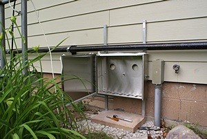
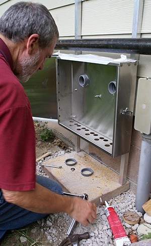
The CEB in position on the east end of the house with the door open. The copper backplane has been removed.
I wanted the CEB anchored at more than two points so I decided to drill two additional holes in the back, one on each side, approximately half way between the existing top and bottom holes. I measured the spacing between the top and bottom holes as carefully as I could. I measured down from the top end of each leg a distance for the top holes that was just sufficient to make sure the door of the CEB was below the 2″ iron gas pipe that runs horizontally along the outside of the house. I measured down from there for the new middle hole and the bottom hole. I then drilled the three holes through each leg by drilling opposing sides. I had to use a powered hand drill for this work as my drill press was stored behind a large pile of RV furniture that we took out of the bus and was inaccessible.
I attached one of the legs to the back of the box using two short bolts through the top and bottom holes. I then used the middle hole in the leg as a guide and drilled through the back of the CEB. I repeated this procedure for the other leg. I drilled the holes in the legs as accurately as I could but they did not quite line up so I had to enlarge them slightly by using the drill bit like a router bit. Not ideal, to be sure, but aluminum is relatively soft and it worked.
The east end of the house with two 2″ holes for the conduit.
I attached each leg to the back of the CEB using 1.5″ 1/4-20 bolts through the bottom corner holes. I snugged these up but left them loose enough that we could move the legs. The top and middle holes were located in positions that would allow lag screws to be screwed into the siding and underlying plywood. We had to tilt the legs to get them under the 2″ iron gas pipe and then straighten them and set them on the foundation paver. We had to do this multiple times but it was easy once we figured out how to do it the first time.
With the CEB in position I marked the location of the holes for four 3″ 1/4-20 lag screws. We removed the CEB so I could drill the holes for the lag screws and then put it back in position and screwed it to the wall. I marked the locations of the two holes for the conduit as best I could and then unscrewed the box and removed it again. I used our 1/2″ Craftsmen corded drill for the 3″ hole saw. I bought this drill in 1978, along with a lot of other Craftsmen tools, when we moved into our house in Farmington Hills. I still have almost all of those tools and they all still work.
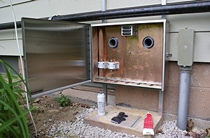
The CEB in position with both pieces of conduit through the back.
With the conduit holes drilled I cut one of the 18″ lengths of conduit in half, inserted the pieces into the adapters, and placed them in the holes. We then put the CEB into position, got the adapters through the holes in the back of the CED, and tried to line up the holes in the legs. The conduit was being forced up as it went through the bond, especially the one on the left, and would not allow the holes in the CEB to line up with the holes in the legs. We took the retaining rings off of the adapters and removed the CEB, again.
I shortened the conduit pieces to approximately 5″ and checked the fit in the holes. We wrapped two bands of adhesive backed foam weather-stripping around each piece of conduit and placed them back in the holes. I then applied a bead of adhesive caulk all the way around each adapter at the wall. We put the CEB in position for the final time, got the conduit adapters through the holes, snugged up the retaining rings, and put the four lag screws in. After tightening the four lag screws I tightened the two bolts in the lower corners. I then tightened the adapter retain rings and put the open end caps on. The conduit ended up getting pulled back out of the wall a bit so I used the thin end of a 10″‘wood shim to try and force the caulk back into the gap around the conduit adapter. It did not go back in very well so I will have to figure out something else to seal around the conduit.
The CEB was finally installed and very solidly anchored. I got the copper base plate and remounted it to the five studs (four corners and one center) using some antioxidant/anti-seize compound on the stud threads. The last step (for today) was to install the snap in covers for the 16 cable entrance holes in the bottom of CEB. I also ordered 16 grommets and will remove the caps and replace them with grommets as I install devices and run their cables and wires into the CEB.
The CEB with the copper backplane installed and the three Morgan lightning arrestors mounted (two lower left, one top center).
The two pieces of conduit open into the sump pump room (large closet) in the northeast corner of the basement just above the wood plate that sits on top of the concrete block foundation. I plan to install the SureCall Fusion5s 5-band cellular booster (amplifier) in this room to keep it close to the CEB and because there is AC power available there. I bought an installation kit for the Fusion5s that includes a lightning arrestor which will get mounted in the CEB. I also bought an amplifier for the OTA TV antenna that will mount on the tower a few feet below the antenna. The amplifier will get its power through the coax from a power inserter that doubles as a lightning arrestor and will be installed in the CEB with the AC power supply (wall wart) in the sump pump room.
I did not get these two additional lightning arrestors installed today. By the time we got the CEB installed we were tired. The high temperature was OK (near 80?) but the relative humidity was very high. I was also very sore the whole time, especially my left knee, undoubtedly the lingering after effect of using the power chisel earlier in the week to remove thinset and mastic from the floor of the bus. Getting down and up at least 50 times during the afternoon did not improve matters, but we got it done.
Even though she was also tired, once we reached a point where I could finish up alone Linda got busy making several food items for tomorrow. In the midst of all that she heated some Amy’s Lentil Soup and made grilled cheese sandwiches with Diaya cheese or dinner. Diaya makes an excellent non-dairy cheese that works well cold or cooked into dishes.
After dinner I returned a call from Butch to find out more about their new property and buildings, and discuss bus and ham radio projects. One of the things Linda made was an apple pie so we stayed up until it was cool enough to wrap up. That turned out to be 10 PM, by which time we ready to turn in for the night.